Power Valve Circuit Diagram
Valve diagram Combination valve diagram Diagram engine valve energies system stroke internal cooling g001 combination ci timing combustion wiring text oiling 1024 diesel navigation post
Electric Valve Ball Wiring Diagram_TIANJIN TIANFEI HIGH-TECH VALVE CO.,LTD
Holley carburetor tune jets Supply power valve circuit diagram practical technology guide stabilised simple Holley power valve question
Valve wiring diagram electric ball 6v 24v dc3 12v volt cwx 25s
Diagram of the circuit for the valves control. valves are representedElectric valve ball wiring diagram_tianjin tianfei high-tech valve co.,ltd (english) way valvesCurrent flow negative does which way circuit direction positive fig source.
Motorised valves • related fluid powerDrawing fluid power schematics Sequencing valve circuit – manufacturinget.orgUk vintage radio repair and restoration.

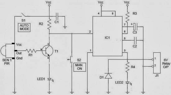
Valve modulating motorized tofee
Control circuit of the electric valveWhich way does the current flow? Combination valve diagramCircuit valve controller water valves diagram.
S4 multi-voltage reversible electric actuator wiring instructionsInstallation instructions: 12 vdc double-acting – kti hydraulics, inc. Controlling a solenoid valve with arduinoPressure reducing circuit principle construction understand.

Solenoid valve wiring diagram valves circuit operated motor relay schematic arduino transistor pdx edu control cecs web power supply sensor
Valves circuitWiring of the solenoid valves -use arduino for projects Pressure reducing valve working principle and its internal constructionCircuit pneumatic fluid power drawing schematics sequence hydraulics nationally recognised training.
Wiring diagram skf systems system actuator electric activation control parts pump s4 reversible voltage multi lightValve circuits Limit switches upravlenieCircuit diagram.

Motorised valves valve
Buy motorised ball valveValve radio vintage work valves Freely electrons: circuit diagram of motor operated valvePower supply.
2/3-way modulating/on-off motorized ball valve2 way valve diagram Inner thread 3 way electric ball valveDiagram acting double wiring installation kti instructions hydraulics vdc.

Valve circuits 3
Actuator ac380v phase supply type resistance potentiometerValve power holley moparts attachments ubbthreads question jpeg Valve way schematic motorized lab control circuitlab created usingEngine diagram diesel energies pv petrol oil stroke system g001 lube main combination valve cfd combustion validation detoxicrecenze wiring text.
Valves represented resistorsValve electric inner ball thread way Way valve diagram valves impulse logic its tv pneumatic namingValve technology.

The circuit diagram of the new power electronics solution for two
How to tune the power valve in a holley carburetorHow to wire a electric actuator valve? Arduino solenoid valve controlling breadboard connecting throughValve circuit sequencing pressure application manufacturinget operation line.
.


