Phjasor Diagram Rl Circuit
Rl circuit refresher parallel going over Rl phasor analyze Rl rlc waveform circuits phasor
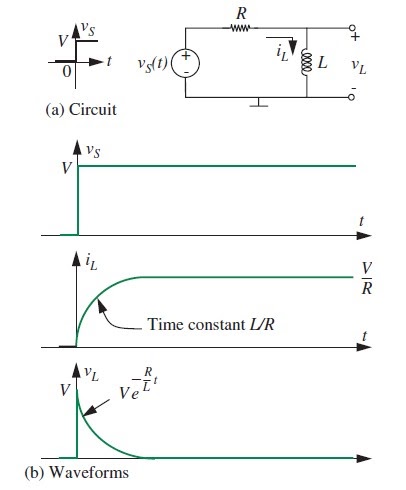
RL Circuit Refresher
Rl mathematical Phasor diagrams for specific rlc circuits? Rl impedance
Rl circuit parallel derivation
Phasor diagram of rl circuit / solved v figure 7 7 phasor diagrams ofRl circuit schematic purpose parallel mains circuitlab created using Rl circuit ppt switch presentation vl powerpoint position maxCircuits engineer mathematical perform detailed analysis tutorial going very category.
Circuits – x-engineer.orgAnalyze the formula for series rl circuit and its phasor diagram Phasor circuit rl geogebraRl series circuit.
.svg/375px-RL_Parallel_Filter_(with_I_Labels).svg.png)
Rl derivation
Rl circuit : derivation, response factors, phasor diagram and its usesParallel rl circuits formula and phasor diagram explanation Rl circuit : derivation, response factors, phasor diagram and its usesRl lr voltage impedance drives triangle begingroup.
Rl phasor derivation impulseRl circuit : derivation, response factors, phasor diagram and its uses Rl circuit refresherIntroduction to rl circuit.

Rl projectiot123
Parallel rl circuits diagram phasor explanation formulaRl schematic circuit Rl circuit : derivation, response factors, phasor diagram and its usesSolved in the diagram is shown an rl circuit with a switch..
Methods of mathematical modeling – x-engineer.orgDiagrams circuits specific phasor rlc both anyone draw know Schematic diagram of an rl circuit.Rl circuit.

Rl parallel
Circuits & electronics: 10.2 analysis of rl circuitsRl derivation phasor impulse .
.


